Installation & applications

Installation – Mechanical
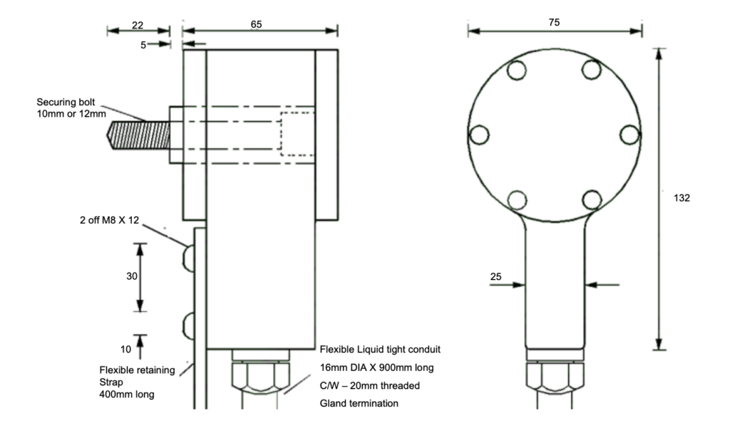
- Select a suitable shaft to install the ‘Rotech’ unit to.
- Use a 5mm drill to drill a pilot hole to a depth of 25mm into the centre of the end of the shaft.
- Use a 10mm drill to open the hole to the required tapping size.
IMPORTANT! Take care that the shaft is drilled centrally.
- Tap the 10mm X 25mm deep hole 12mm UNC.
- Remove the rear cover the Motion Sensor/Encoder and using a 10mm UNC socket wrench install the unit onto the shaft. Re-fit the rear cover.
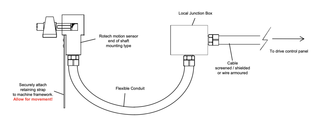
- Bolt the flexible securing strap to any convenient part of the machine frame work
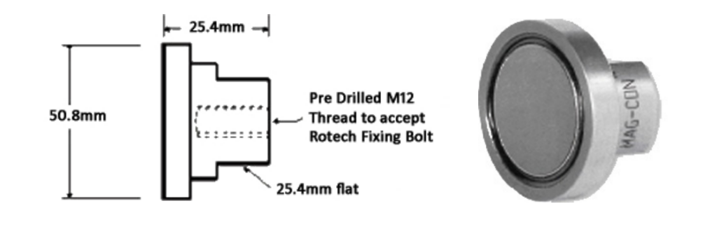
As an alternative method of securing the Rotech end of shaft unit without the need for drilling the
shaft, our unique Magcon unit can be used as shown below – see product data sheets for full
details.
MAG‐CON
MAGNETIC CONNECTOR
For quick and easy installation of Rotech shaft mounted sensors & encoders
Installation – Electrical
- Always complete the mechanical installation before commencing the electrical installation.
- Install a suitable junction box within 300 – 600mm of the Motion Sensor/Encoder.
- Gland – Off the flexible conduit of the Motion Sensor/Encoder in the junction box and connect
the 2 or 3 wires to suitable terminals. (The flexible conduit and cable are supplied over-length
they can be cut back and shortened as required) - Connect suitable wires and cable to route the Shaft Encoder signal back to the control panel.
Important
The maximum distance recommended between the Motion Sensor/Encoder and the control
panel is 1000 yards.
Armoured or screened cable should be used id the cable is routed in the vicinity of power
cables.
Do not route the Motion Sensor/Encoder signal through multi-core cables carrying other
signals or voltages.
Other Applications
Motion Sensors/Encoders are used extensively in many different industries for a wide variety of
applications.
Besides measuring the speed of a rotating shaft, they can determine direction of rotation, angular
position, and the number of revolutions or parts of revolutions completed.
Using screws, slides, racks & pinions these angular functions can be translated into linear or length
functions.
The following are the more popular applications that ‘Rotech’ Heavy Duty Motion Sensors/Encoders are utilised for.
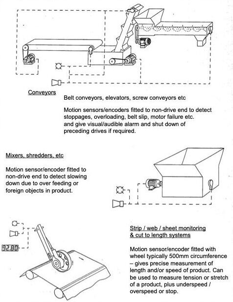
Speed Indication
Used in conjunction with a Digital Panel Meter to display RPM or linear speed of a Conveyor Belt.
Length Measurement
Used in conjunction with a Counter unit and either a roller or wheel of known circumference, to
measure cut-off lengths, total throughput, or to position material for a process operation.
Direction Indication
Using a ‘Rotech’ Heavy Duty Motion Sensor/Encoder with dual quadrature outputs, direction of
rotation can be determined.
This is most frequently used to detect if a heavily loaded conveyor starts to run backwards.
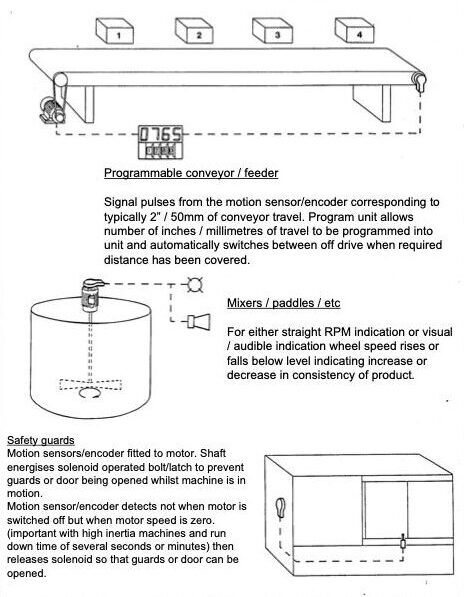
Practical Applications
Sensor Types Explained
| N | 2 wire – NAMUR intrinsically Safe-Hazardous Areas 8.2 VDC |
| E | 3 wire 10 – 30 VDC – NPN transistor – current sink |
| E2 | 3 wire 10 – 30 VDC PNP transistor – current source |
| E3 | 3 wire 10 – 30 VDC NPN/PNP transistor (Sink/Source) |
| E4 | 2 wire 10 to 36 VDC – NPN/PNP transistor (Sink/Source) bipolar (Can be used in place of E3 type) |
| E3Q | 4 wire 10 – 30VDC – 2x NPN/PNP Transistor (Sink/Source – Quadrature Configuration) |
| NQ | 2x 2 wire – N Type (as shown above) – Quadrature Configuration |
| EQ | 2x 3 wire – E Type (as shown above) – Quadrature Configuration |
| E2Q | 2x 3 wire – E2 Type (as shown above) – Quadrature Configuration |
| W | 2 wire, 20 – 240 VAC/DC (Max Switching Frequency 25Hz AC, 100Hz DC) |
Rotech sensor output type E, E2, E3
Connect a 0 to 30vdc voltmeter between brown and blue connections
Voltmeter should indicate D.C. Supply voltage of between 10 and 30vdc
Now Connect the voltmeter between the black and blue connections.
Rotate Rotech unit very slowly, voltmeter should indicate on/off pulses between 0vdc and the nominal
Supply Voltage (Supply Voltage Minus 1 To 2 Vdc)
Rotech sensor type N
Connect a 0 to 10ma multimeter in series with the blue wire connecting the Rotech unit to it’s control circuit
rotate the Rotech unit very slowly, multimeter should indicate on / off pulses of less than 1ma to greater than 3ma.
See note * 1 below
Rotech sensor type W
Connect a 0 to 240vac voltmeter between the brown connection and 0 vac, verify the supply voltage is present.
Now connect the voltmeter between the blue connection and 0 vac.
Rotate the Rotech unit very slowly, the voltmeter should indicate on / off pulses of between 0v and the supply voltage.
See note * 1 below
Note * 1
- At higher speeds the meter will not respond quickly enough to the on / off pulses. It will display an average value between
The max and min levels. - The number of on / off pulses
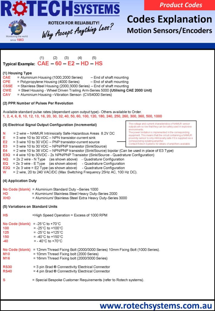
Part Numbers Explained